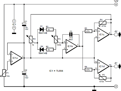
The circuit consists of integrator IC1b, whose output is applied to comparator IC1c. The output of the comparator is a rectangular signal The output of IC1b is raised by amplifier IC1d to a level that allows the full output voltage range of the operational amplifier to be used. Op amp IC1a provides a stable virtual earth, whose level is set to half the supply voltage with P1. The smooth setting of the frequency is made possible by feedback of part of the output of the comparator to the input of the integrator via P2. This preset is usually not provided in standard triangle-wave generators. Network D1-R1-D2-R2-P3 makes it possible to give integrator capacitor C3 different charging and discharge times.
Simple Function Generator Circuit Diagram
This arrangement enables the output signal at A1 and the duty cycle of the rectangular wave signal at A2 to be varied. Varying the amplification factor with P5 has no effect on the frequency set with P2. The slope of the signal edges, the transient responses, and the output voltage range (rail-to-rail or with some voltage drop) depend on the type of op amp used. The TL084 used in the prototype offers a good compromise between price and meeting the wanted parameters. The circuit is best built on a small piece of prototyping board. The circuit draws a current of not more than 12 mA.
Brief parameters:
Provides triangle-wave, sawtooth or rectangular signal
Waveform variable independently of frequency (triangle wave and sawtooth)
Duty cycle of rectangular signal can be set independently of frequency
Applications:
Test and measurement
Pulse-width control
Summary of preset action:
P1 – sets virtual earth to a level equal to Ucc/2;
P2 – sets the frequency;
P3– sets the waveform;
P4 – sets the hysteresis of the comparator (frequency and amplitude of the triangle-wave signal)
P5 – sets the amplification of the triangle-wave and sawtooth signals.
Source: Extremecircuits.net


Post a Comment