Electrical Isolation For I2C Bus

When the SDA (Serial DAta) lines on both the left and right lines are 1, the circuit is quiescent and optoisolators IC1 and IC2 are not actuated. When the SDA line at the left becomes 0, current flows through the LED in IC1 via R2. The SDA line at the right is then pulled low via D2 and IC1. Optoisolator IC2 does not transfer this 0 to the left, because the polarity of the LED in IC2 is the wrong way around for this level. This arrangement prevents the circuit holding itself in the 0 state for ever. As is seen, the circuit is symmetrical. So, when the SDA line at the right is 0, this is transferred to the left. The lower part of the diagram, intended for the SCL (Serial CLock) line, is identical to the upper part.


Electrical Isolation For I2C Bus Circuit Diagram

Resistors R1, R4, R5, and R8, are the usual 3.3 kΩ pull-up resistors that are obligatory in each I2C line. If these resistors are already present elsewhere in the system, they may be omitted here. The current drawn by the circuit is slightly larger than usual since the pull-up resistors are shunted by the LEDs in the optoisolators and their series resistors. Nevertheless, it remains within the norms laid down in the I2C

Source: Extremecircuits.net

Power Flip-Flop Using A Triac

Modern electronics is indispensable for every large model railroad system, and it provides a solution to almost every problem. Although ready-made products are exorbitantly expensive, clever electronics hobbyists try to use a minimum number of components to achieve optimum results together with low costs. This approach can be demonstrated using the rather unusual semiconductor power flip-flop described here. A flip-flop is a toggling circuit with two stable switching states (bistable multivibrator). It maintains its output state even in the absence of an input pulse.

Flip-flops can easily be implemented using triacs if no DC voltage is available. Triacs are also so inexpensive that they are often used by model railway builders as semiconductor power switches. The decisive advantage of triacs is that they are bi-directional, which means they can be triggered during both the positive and the negative half-cycle by applying an AC voltage to the gate electrode (G). The polarity of the trigger voltage is thus irrelevant. Triggering with a DC current is also possible. Figure 1 shows the circuit diagram of such a power flop-flop. A permanent magnet is fitted to the model train, and when it travels from left to right, the magnet switches the flip-flop on and off via reed switches S1 and S2.

Circuit diagram:

In order for this to work in both directions of travel, another pair of reed switches (S3 and S4) is connected in parallel with S1 and S2. Briefly closing S1 or S3 triggers the triac. The RC network C1/R2, which acts as a phase shifter, maintains the trigger current. The current through R2, C1 and the gate electrode (G) reaches its maximum value when the voltage across the load passes through zero. This causes the triac to be triggered anew for each half-cycle, even though no pulse is present at the gate. It remains triggered until S2 or S4 is closed, which causes it to return to the blocking state.The load can be incandescent lamps in the station area (platform lighting) or a

solenoid-operated device, such as a crossing gate. The LED connected across the output (with a rectifier diode) indicates the state of the flip-flop. The circuit shown here is designed for use in a model railway system, but there is no reason why it could not be used for other applications. The reed switches can also be replaced by normal pushbutton switches. For the commonly used TIC206D triac, which has a maximum current rating of 4 A, no heat sink is necessary in this application unless a load current exceeding 1 A must be supplied continuously or for an extended period of time. If the switch-on or switch-off pulse proves to be inadequate, the value of electrolytic capacitor C1 must be increased slightly.
Author: R. Edlinger - Copyright: Elektor July-August 2004

Mains Voltage Monitor

Many electronics hobbyists will have experienced the following: you try to finish a project late at night, and the mains supply fails. Whether that is caused by the electricity board or your carelessness isn’t really important. In any case, at such times you may find yourself without a torch or with flat batteries. There is no need to panic, as this circuit provides an emergency light. When the mains fails, the mains voltage monitor turns on five super bright LEDs, which are fed from a 9 V battery (NiCd or NiMH) or 7 AA cells. A buzzer has also been included, which should wake you from your sleep when the mains fails.

You obviously wouldn’t want to oversleep because your clock radio had reset, would you? When the mains voltage is present, the battery is charged via relay Re1, diode D8 and resistor R10. D8 prevents the battery voltage from powering the relay, and makes sure that the relay switches off when the mains voltage disappears. R10 is chosen such that the charging current of the battery is only a few milliamps. This current is small enough to prevent over-charging the battery. D6 acts as a mains indicator. When the relay turns off, IC1 receives power from the battery. The JK flip-flops are set via R12 and C4.

Circuit diagram:
Mains Voltage Monitor Circuit Diagram

This causes T1 and T2 to conduct, which turns on D1-D5 and the buzzer. When the push button is pressed, a clock pulse appears on the CLK input of flip-flop IC1b. The output then toggles and the LEDs turn off. At the same time IC1a is reset, which silences the buzzer. If you press the button again, the LEDs will turn on since IC1b receives another clock pulse. The buzzer remains off because IC1a stays in its reset state. R11, R3 and C3 help to debounce the push button signal. In this way the circuit can also be used as a torch, especially if a separate mains adapter is used as the power supply.

As soon as the mains voltage is restored, the relay turns on, the LEDs turn off and the battery starts charging. The function of R13 is to discharge C4, preparing the circuit for the next mishap. If mains failures are a regular occurrence, we recommend that you connect pairs of LEDs in series. The series resistors should then have a value of 100 ?. This reduces the current consumption and therefore extends the battery life. This proves very useful when the battery hasn’t recharged fully after the last time. In any case, you should buy the brightest LEDs you can get hold of. If the LEDs you use have a maximum current of 20 mA, you should double the value of the series resistors! You could also consider using white LEDs.
Author: Goswin Visschers - Copyright: Elektor July-August 2004

Mains Slave Switcher

There are many situations where two or more pieces of equipment are used together and to avoid having to switch each item on separately or risk the possibility of leaving one of them on when switching the rest off, a slave switch is often used. Applications which spring to mind are a computer/printer/scanner etc or audio amplifier/record deck/tuner combinations or perhaps closest to every electronics enthusiast’s heart, the work bench where a bench power supply/oscilloscope/soldering iron etc are often required simultaneously.

The last is perhaps a particularly good example as the soldering iron, often having no power indicator, is invariably left on after all the other items have been switched off. Obviously the simplest solution is to plug all of the items into one extension socket and switch this on and off at the mains socket but this is not always very convenient as the switch may be difficult to reach often being behind or under the work bench. Slave switches normally sense the current drawn from the mains supply when the master unit is switched on by detecting the resulting voltage across a series resistor and switching on a relay to power the slave unit(s).


This means that the Live or Neutral feed must be broken to allow the resistor to be inserted. This circuit, which is intended for switching power to a work bench when the bench light is switched on, avoids resistors or any modifications to the lamp or slave appliances by sensing the electric field around the lamp cable when this is switched on. The lamp then also functions as a ‘power on’ indicator (albeit a very large one that cannot be ignored) that shows when all of the equipment on the bench is switched on.

The field, which appears around the lamp cable when the mains is connected, can be sensed by a short piece of insulated wire simply wrapped around it and this is amplified by the three stage amplifier which can be regarded as a single super-transistor with a very high gain. The extremely small a.c. base current results in an appreciable collector current which after smoothing (by C3) is used to switch on a relay to power the other sockets. Power for the relay is obtained from a capacitor ‘mains dropper’ that generates no heat and provides a d.c. supply of around 15 volts when the relay is off.

Circuit diagram:
Mains Slave Switcher Circuit Diagram

The output current of this supply is limited so that the voltage drops substantially when the relay pulls in but since relays require more current to operate them than they do to remain energized, this is not a problem. Since the transistor emitter is referenced to mains Neutral, it is the field around the mains Live which will be detected. Consequently, for correct operation the Live wire to the lamp must be switched and this will no doubt be the case in all lamps where the switch is factory fitted. In case of uncertainty, a double-pole switch to interrupt both the Live and Neutral should be used.

The sensitivity of the circuit can be increased or decreased as required by altering the value of the T2 emitter resistor. The sensing wire must of course be wrapped around a section of the lamp lead after the switch otherwise the relay will remain energized even when the lamp has been switched off. The drawing shows the general idea with the circuit built into the extension socket although, depending on the space available an auxiliary plastic box may need to be used.

Warning:
The circuit itself is not isolated from the mains supply so that great care should be taken in its construction and testing. The sensor wire must also be adequately insulated and the circuit enclosed in a box to make it inaccessible to fingers etc. when it is in use.

Mains Slave Switcher II

As a guide, a one-inch reed switch with 40 turns reliably switched on with the current flowing through a 150-watt lamp (approx. 625 mA) but larger reeds may require more turns. If the master appliance draws less current (which is unlikely with power tools) more turns will be required. The reed switch is used to switch on transistor T1 which in turn switches the relay RE1 and powers the slave appliance. Since reed switches have a low mechanical inertia, they have little difficulty in following the fluctuations of the magnetic field due to the alternating current in the coil and this means that they will switch on and off at 100 Hz.

Circuit diagram:
Mains Slave Switcher II Circuit Diagram

C3 is therefore fitted to slow down the transistor response and keep the relay energised during the mains zero crossings when the current drawn by the appliance falls to zero and the reed switch opens. C1 drops the mains voltage to about 15 V (determined by zener diode D1) and this is rectified and smoothed by D2 and C2 to provide a d.c. supply for the circuit. The relay contacts should be rated to switch the intended appliance (vacuum cleaner) and the coil should have a minimum coil resistance of 400 R as the simple d.c. supply can only provide a limited current. C1 drops virtually the full mains voltage and should therefore be a n X2-class component with a voltage rating of at least 250V a.c.

Warning:
The circuit is by its nature connected directly to the mains supply. Great care should therefore be taken in its construction and the circuit should be enclosed in a plastic or earthed metal box with mains sockets fitted for the master and slave appliances.
Author: Elektor - Copyright: Elektor Electronics Magazine

Mains Frequency Monitor

Here is a simple frequency counter designed to monitor the 240VAC mains supply. It as a frequency range of 0-999Hz, so it could also be used with 400Hz equipment. Standard TTL/CMOS logic is employed for the counters and display drivers, while an ELM446 (IC1) generates accurate 1Hz pulses for gating. This device utilizes a 3.579545MHz crystal for its timebase, as commonly found in TV and video circuits and even on old PC motherboards.

Circuit diagram:

Mains Frequency Monitor Circuit Diagram
Copyright: Silicon Chip Electronics Magazine

Smart Trailing Socket

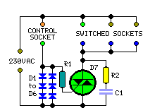
Mains sockets switched automatically by a Control Socket, Up to 1000W switched power

This circuit consists of a Trailing Socket (also called Extension or Distribution Socket) or similar device where two, three or more sockets (depending on the box dimensions and on constructor's needs) will be powered only when a current flows in the Control Socket. For example: if an electric drill is connected to the Control Socket, the Switched Sockets will be powered each time the electric drill is running. In this case, a lamp could be connected to a Switched Socket and will illuminate when the drill is operating.

Another example: a desk lamp could be connected to the Control Socket and a PC, a Monitor and a Printer could be connected to the Switched Sockets and will be running after the lamp is switched on. Switching off the lamp, all the above mentioned appliances will be automatically switched off. A further application is the control of a High Fidelity chain, plugging the Power Amplifier in the Control Socket and - for example - CD Player, Tape Recorder, and Tuner in the Switched Sockets.

Usually, trailing sockets are placed to the rear of the appliances, often in places not easily reachable, so, even if the socket has a switch, it is much easier to switch on and off the High Fidelity chain from the main amplifier itself. The same consideration is valid for computer-monitor-printer chains etc. Nevertheless, in this case, the use of a table lamp plugged in the Control Socket is almost mandatory, as explained below. In fact, this very sensitive circuit works fine when appliances having full breaking switches like lamps, drills, most power amplifiers, old radios, old TV sets, fans, almost all electrical household appliances etc. are plugged in the Control Socket.

This is because these devices have a switch that fully excludes the internal circuitry from the mains. Unfortunately, in modern devices like computers, monitors, CD players, recent radios and TV sets (usually powered by means of internal "switching" supplies), the power switch does not completely isolate the internal circuitry from the mains, as transient suppressors and other components remain on circuit. This causes a very small current to flow across the sensing circuitry, but sufficient to trigger the output Triac.

Therefore, the switched devices will remain always on, no matter if the control appliance is on or off. This could also happen when devices connected to the mains by means of plug-in power supply adapters are used as control appliances, due to their lack of a mains switch. In spite of this restriction, the circuit can be still useful, due to the high number and variety of devices allowing impeccable performance when they are plugged in the Control Socket.

Circuit diagram:
Smart Trailing Socket Circuit Diagram
Parts:

R1,R2_________100R 1/2W Resistors
C1____________100nF 630V Polyester Capacitor
D1 to D6_____1N5408 1000V 3A Diodes (See Notes)
D7__________TIC225M 600V 8A Sensitive Gate Triac (See Notes)
A commercial trailing socket to be modified or a self-made box with several sockets.

Circuit operation:

Six back-to-back power diodes are connected in series to the Control Socket. The current drawn by the device plugged into this socket when in the on state, flowing through the diode chain, causes a voltage drop of about 2V. This voltage, limited by R1, drives the Gate of the Triac D7 which, in turn, will switch the output sockets. C1 and R2 form a so called "Snubber network", helping to eliminate switching transients generated by inductive loads.

Notes:
  • The circuit is sufficiently small to be embedded into some types of commercial trailing sockets, or a box with a number of sockets can be made at will.
  • The diode types suggested in the Parts List for D1 to D6 will allow an appliance of up to about 500W power to be plugged in the Control Socket. Use BY550-800 diodes for up to 800 - 1000W.
  • For less demanding appliances, 1N4007 diodes will allow up to 200W power.
  • The Triac type suggested in the Parts List for D7 will allow a total power available to the Switched Sockets of more than 1000W. If you intend to drive loads of more than 500W total, please use a suitable heatsink.
  • Wanting to drive less powerful loads, you can use for D7 a TIC216M (up to 800 - 1000W) or a TIC206M (up to 500 - 600W).
  • Warning! The device is connected to 230Vac mains, so some parts in the circuit board are subjected to lethal potential! Avoid touching the circuit when the mains cord is plugged in!
Copyright: www.redcircuits.com

Mains Manager

Very often we forget to switch off the peripherals like monitor, scanner, and printer while switching off our PC. The problem is that there are separate power switches to turn the peripherals off. Normally, the peripherals are connected to a single of those four-way trailing sockets that are plugged into a single wall socket. If that socket is accessible, all the devices could be switched off from there and none of the equipment used will require any modification. Here is a mains manager circuit that allows you to turn all the equipment on or off by just operating the switch on any one of the devices; for example, when you switch off your PC, the monitor as well as other equipment will get powered down automatically.

You may choose the main equipment to control other gadgets. The main equipment is to be directly plugged into the master socket, while all other equipment are to be connected via the slave socket. The mains supply from the wall socket is to be connected to the input of the mains manager circuit. The unit operates by sensing the current drawn by the control equipment/load from the master socket. On sensing that the control equipment is on, it powers up the other (slave) sockets. The load on the master socket can be anywhere between 20 VA and 500 VA, while the load on the slave sockets can be 60 VA to 1200 VA. During the positive half cycle of the mains AC supply, diodes D4, D5, and D6 have a voltage drop of about 1.8 volts when current is drawn from the master socket.

Diode D7 carries the current during negative half cycles. Capacitor C3, in series with diode D3, is connected across the diode combination of D4 through D6, in addition to diode D7 as well as resistor R10. Thus current pulses during positive half-cycles, charge up the capacitor to 1.8 volts via diode D3. This voltage is sufficient to hold transistor T2 in forward biased condition for about 200 ms even after the controlling load on the master socket is switched off. When transistor T2 is ‘on’, transistor T1 gets forward biased and is switched on. This, in turn, triggers Triac 1, which then powers the slave loads. Capacitor C4 and resistor R9 form a snubber network to ensure that the triac turns off cleanly with an inductive load.

Circuit diagram:

LED1 indicates that the unit is operating. Capacitor C1 and zener ZD1 are effectively in series across the mains. The resulting 15V pulses across ZD1 are rectified by diode D2 and smoothened by capacitor C2 to provide the necessary DC supply for the circuit around transistors T1 and T2. Resistor R3 is used to limit the switching-on surge current, while resistor R1 serves as a bleeder for rapidly discharging capacitor C1 when the unit is unplugged. LED1 glows whenever the unit is plugged into the mains. Diode D1, in anti-parallel to LED1, carries the current during the opposite half cycles. Don’t plug anything into the master or slave sockets without testing the unit.

If possible, plug the unit into the mains via an earth leakage circuit breaker. The mains LED1 should glow and the slave LED2 should remain off. Now connect a table lamp to the master socket and switch it ‘on’. The lamp should operate as usual. The slave LED should turn ‘on’ whenever the lamp plugged into slave socket is switched on. Both lamps should be at full brightness without any flicker. If so, the unit is working correctly and can be put into use.

Note:
  1. The device connected to the master socket must have its power switch on the primary side of the internal transformer. Some electronic equipment have the power switch on the secondary side and hence these devices continue to draw a small current from the mains even when switched off. Thus such devices, if connected as the master, will not control the slave units correctly.
  2. Though this unit removes the power from the equipment being controlled, it doesn’t provide isolation from the mains. So, before working inside any equipment connected to this unit, it must be unplugged from the socket.

Fuse Saver

This circuit will be particularly useful to those hobbyists who use a ‘breadboard’ to try out ideas and who also use a simple ‘home-made’ DC power supply consisting of a transformer, rectifier, smoothing capacitor and protective fuse, that is, one without over current protection! In this circuit, the detecting element is resistor R6. Under normal conditions, its voltage drop is not high enough to switch on transistor T1.

The value of R6 can be altered to give a different cut-off current, as determined by Ohm’s Law, if required. When a short circuit occurs in the load, the voltage rises rapidly and T1 starts to conduct. This draws in the relay, switching its contacts, which cuts off power to the external circuit, and instead powers the relay coil directly, latching it in this second state. The circuit remains in this state until the primary power supply is switched off.

Capacitors C1 and C2 hold enough charge (via D3, D4 and D6, which prevent the charge from being lost to the rest of the circuit, whichever state it is in) to keep T1 switched on and power the relay while it switches over, and R2 and R4 provide slow discharge paths. LEDs D1 (red) and D5 (green) indicate what state the circuit is in. Inductor L1 slows the inrush of current when the circuit is switched on, which would otherwise cut off the circuit immediately.

Circuit diagram:
Fuse Saver Circuit Diagram

D2 and D7 provide the usual back-emf protection across the coils. In use, the input of the circuit is connected to the main transformer-rectifier-capacitor-fuse power supply via K1, and the output is connected to the (experimental) load via K2. Note that the input voltage must be a floating supply if Vout– is grounded via the load, as Vin– and Vout– must not be connected together. Some consideration needs to be given to a number of components.

First, the choice of relay Re1. For the prototype, this was obtained from Maplin, part number YX97F. This is has a coil resistance of 320 ?, which with R1 forms the collector load for T1. Its allowed pull-in voltage range is nominally 9 V to 19 V, which limits the input power supply voltage to between around 10 V to 30 V (DC only). R1 could be replaced by a wire link for operation at input voltages below 10 V, or increased in value, as determined by either the application of Ohm’s Law once more or trial and error, for an input voltage above 30 V.

Coil L1 was obtained from Farnell, part number 581-240. Finally, the protective fuse for the input power supply should be a ‘slow-blow’ type; ‘fast’ fuses will rupture before the relay has time to switch. Also note that this device is meant to save fuses, not replace them. A mains transformer must always be fused if it is not designed to run safely, i.e., without presenting a fire hazard, even if its output has a continuous short-circuit fault.
Author: David Clark - Copyright: Elektor Electronics Magazine

Mains Pulser

The pulser is intended to switch the mains voltage on and off at intervals between just under a second and up to 10 minutes. This is useful, for instance, when a mains-operated equipment is to be tested for long periods, or for periodic switching of machinery. Transformer Tr1, the bridge rectifier , and regulator IC1 provide a stable 12V supply rail for IC2 and the relay. The timer is arranged so that the period-determining capacitor can be charged and discharged independently. Four time ranges can be selected by selecting capacitors with the aid of jumpers. Short-circuiting positions 1 and 2 gives the longest time, and short-circuiting none the shortest.

Circuit diagram:

Mains Pulser Circuit Diagram

In the latter case, the 10µF capacitor at pins 2 and 6 of the timer IC determines the time with the relevant resistors. The value of this capacitor may be chosen slightly lower. The two preset potentiometers enable the on and off periods to be set. The 1k resistor in series with one of the presets determines the minimum discharge time. The timer IC switches a relay whose double-pole contacts switch the mains voltage. The LEDs indicate whether the mains voltage is switched through (red) or not (green). The 100mA slow fuse protects the mains transformer and low-voltage circuit. The 4 A medium slow fuse protects the relay against overload.

Simple Electrification Unit

The circuit is intended for carrying out harmless experiments with high-voltage pulses and functions in a similar way as an electrified fence generator. The p.r.f. (pulse repetition frequency) is determined by the time constant of network R1-C3 in the feedback loop of op amp IC1a: with values as specified, it is about 0.5 Hz. The stage following the op amp, IC1b, converts the rectangular signal into narrow pulses. Differentiating network R2-C4, in conjunction with the switching threshold of the Schmitt trigger inputs of IC1b, determines the pulse period, which here is about 1.5 ms. The output of IC1b is linked directly to the gate of thyristor THR1, so that this device is triggered by the pulses.

The requisite high voltage is generated with the aid of a small mains transformer, whose secondary winding is here used as the primary. This winding, in conjunction with C2, forms a resonant circuit. Capacitor C3 is charged to the supply voltage (12 V) via R3.When a pulse output by IC1b triggers the thyristor, the capacitor is discharged via the secondary winding. The energy stored in the capacitor is, however, not lost, but is stored in the magnetic field produced by the transformer when current flows through it. When the capacitor is discharged, the current ceases, whereupon the magnetic field collapses. This induces a counter e.m.f. in the transformer winding which opposes the voltage earlier applied to the transformer.

Circuit diagram:


This means that the direction of the current remains the same. However, capacitor C2 is now charged in the opposite sense, so that the potential across it is negative. When the magnetic field of the transformer has returned the stored energy to the capacitor, the direction of the current reverses, and the negatively charged capacitor is discharged via D1 and the secondary winding of the transformer. As soon as the capacitor begins to be discharged, there is no current through the thyristor, which therefore switches off. When C2 is discharged further, diode D1 is reverse-biased, so that the current loop to the transformer is broken, whereupon the capacitor is charged to 12 V again via R3. At the next pulse from IC1b, this process repeats itself.

Since the transformer after each discharge of the capacitor at its primary induces not only a primary, but also a secondary voltage, each triggering of the thyristor causes two closely spaced voltage pulses of opposite polarity. These induced voltages at the secondary, that is, the 230 V, winding, of the transformer are, owing to the higher turns ratio, much higher than those at the primary side and may reach several hundred volts. However, since the energy stored in capacitor C2 is relatively small (the current drain is only about 2 mA), the output voltage cannot harm man or animal. It is sufficient, however, to cause a clearly discernible muscle convulsion.
Author: P. Lay
Copyright: Elektor Electronics

Mini High-Voltage Generator

Here’s a project that could be useful this summer on the beach, to stop anyone touching your things left on your beach towel while you’ve gone swimming; you might equally well use it at the office or workshop when you go back to work. In a very small space, and powered by simple primary cells or rechargeable batteries, the proposed circuit generates a low-energy, high voltage of the order of around 200 to 400 V, harmless to humans, of course, but still able to give a quite nasty ‘poke’ to anyone who touches it.

Quite apart from this practical aspect, this project will also prove instructional for younger hobbyists, enabling them to discover a circuit that all the ‘oldies’ who’ve worked in radio, and having enjoyed valve technology in particular, are bound to be familiar with. As the circuit diagram shows, the project is extremely simple, as it contains only a single active element, and then it’s only a fairly ordinary transistor. As shown here, it operates as a low-frequency oscillator, making it possible to convert the battery’s DC voltage into an AC voltage that can be stepped up via the transformer.

Using a centre-tapped transformer as here makes it possible to build a ‘Hartley’ oscillator around transistor T1, which as we have indicated above was used a great deal in radio in that distant era when valves reigned supreme and these was no sign of silicon taking over and turning most electronics into ‘solid state’. The ‘Hartley’ is one of a number of L-C oscillator designs that made it to eternal fame and was named after its invertor, Ralph V.L Hartley (1888-1970). For such an oscillator to work and produce a proper sinewave output, the position of the intermediate tap on the winding used had to be carefully chosen to ensure the proper step-down (voltage reduction) ratio.

Here the step-down is obtained inductively. Here, optimum inductive tapping is not possible since we are using a standard, off-the-shelf transformer. However we’re in luck — as its position in the centre of the winding creates too much feedback, it ensures that the oscillator will always start reliably. However, the excess feedback means that it doesn’t generate sinewaves; indeed, far from it. But that’s not important for this sort of application, and the transformer copes very well with it.

The output voltage may be used directly, via the two current-limiting resistors R2 an R3, which must not under any circum-stances be omitted or modified, as they are what make the circuit safe. You will then get around 200 V peak-to-peak, which is already quite unpleasant to touch. But you can also use a voltage doubler, shown at the bottom right of the figure, which will then produce around 300 V, even more unpleasant to touch. Here too of course, the resistors, now know as R4 and R5, must always be present. The circuit only consumes around a few tens of mA, regardless of whether it is ‘warding off’ someone or not! If you have to use it for long periods, we would however recommend powering it from AAA size Ni-MH batteries in groups of ten in a suitable holder, in order not to ruin you buying dry batteries.

Circuit diagram:

Warning!If you build the version without the voltage doubler and measure the output voltage with your multimeter, you’ll see a lower value than stated. This is due to the fact that the waveform is a long way from being a sinewave, and multimeters have trouble interpreting its RMS (root-mean-square) value. However, if you have access to an oscilloscope capable of handling a few hundred volts on its input, you’ll be able to see the true values as stated. If you’re still not convinced, all you need do is touch the output terminals...

To use this project to protect the handle of your beach bag or your attachecase, for example, all you need do is fix to this two small metallic areas, quite close together, each connected to one output terminal of the circuit. Arrange them in such a way that unwanted hands are bound to touch both of them together; the result is guaranteed! Just take care to avoid getting caught in your own trap when you take your bag to turn the circuit off!

..::: Do not built this circuit if your not an EXPERT :::..
Elektor Electronics 2008

Electrical Isolation For I2C Bus

When the SDA (Serial DAta) lines on both the left and right lines are 1, the circuit is quiescent and optoisolators IC1 and IC2 are not actuated. When the SDA line at the left becomes 0, current flows through the LED in IC1 via R2. The SDA line at the right is then pulled low via D2 and IC1. Optoisolator IC2 does not transfer this 0 to the left, because the polarity of the LED in IC2 is the wrong way around for this level. This arrangement prevents the circuit holding itself in the 0 state for ever. As is seen, the circuit is symmetrical. So, when the SDA line at the right is 0, this is transferred to the left. The lower part of the diagram, intended for the SCL (Serial CLock) line, is identical to the upper part.


Electrical Isolation For I2C Bus Circuit Diagram

Resistors R1, R4, R5, and R8, are the usual 3.3 kΩ pull-up resistors that are obligatory in each I2C line. If these resistors are already present elsewhere in the system, they may be omitted here. The current drawn by the circuit is slightly larger than usual since the pull-up resistors are shunted by the LEDs in the optoisolators and their series resistors. Nevertheless, it remains within the norms laid down in the I2C specification.